

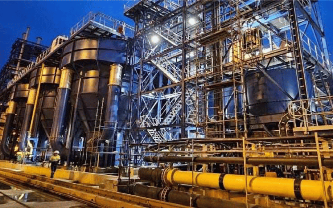
Project Overview
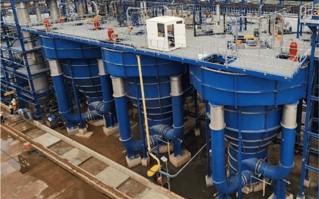
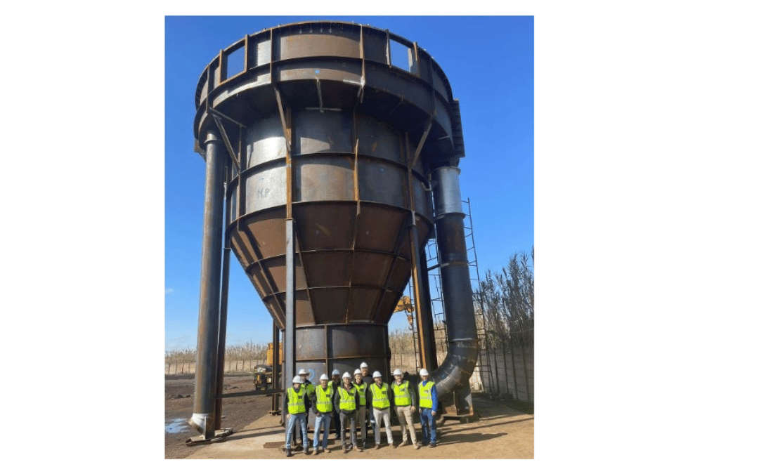
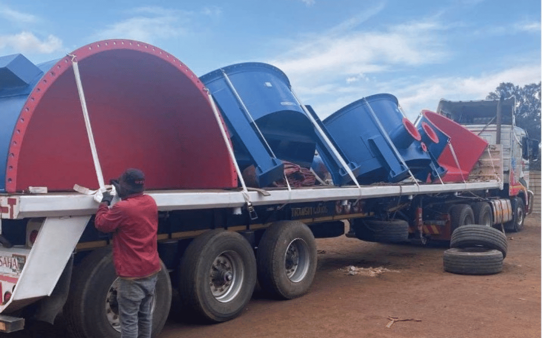
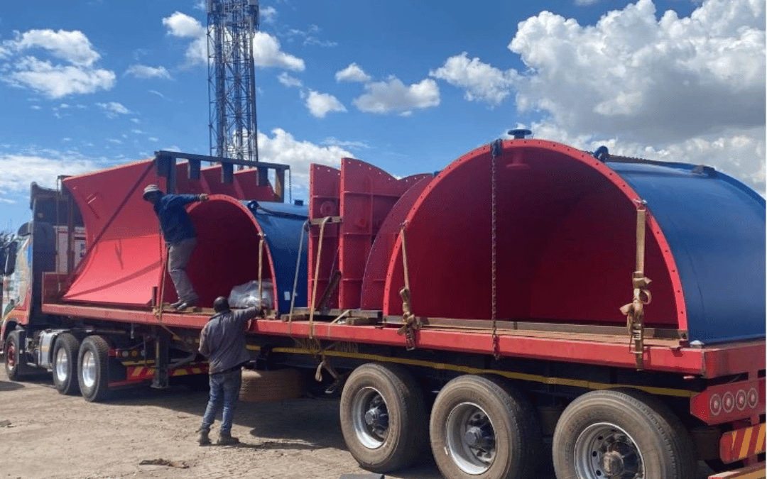
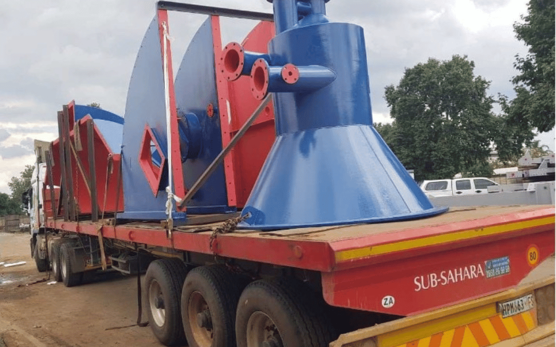
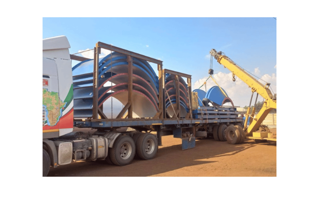
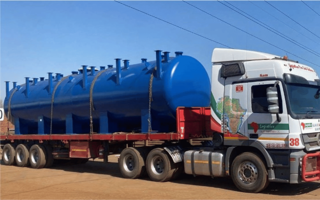
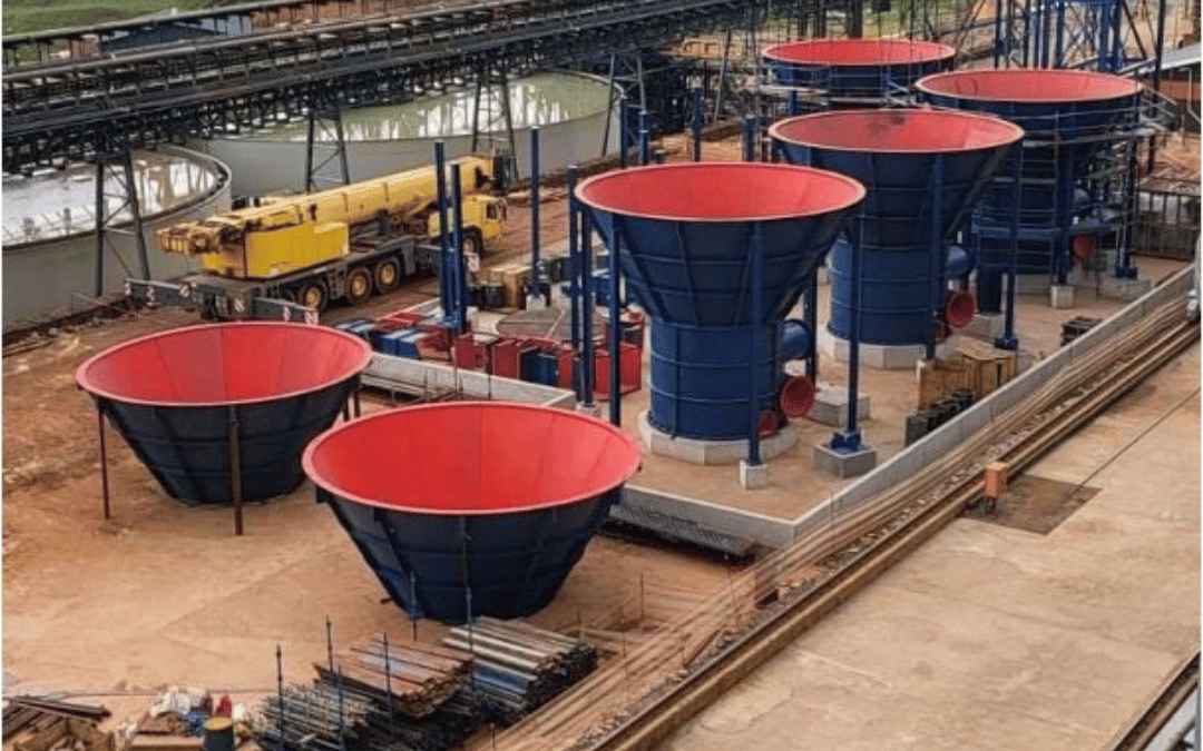
The Azmet Reactors project, exemplifies precision engineering, showcasing intricate design and fabrication processes. A collaborative effort led by Viva Engineering, the project involved creating six innovative reactors. These reactors, with a diameter of 9.9 meters and height of 11 meters, demanded exacting tolerances. Using structural steel and advanced modeling, Viva Engineering achieved impeccable alignment and structural integrity, with 3265 precise welds. Transportation posed significant challenges due to size, but meticulous planning allowed for secure shipping to the Democratic Republic of Congo. This feat of engineering, from design to transportation, underscores the steel industry's capability to execute complex projects with precision.
PROJECT OBJECTIVE & REQUIREMENTS:
• To design a 320 m3 capacity CRP Vessel to process fluid with a bulk density of 1800 kg/m3
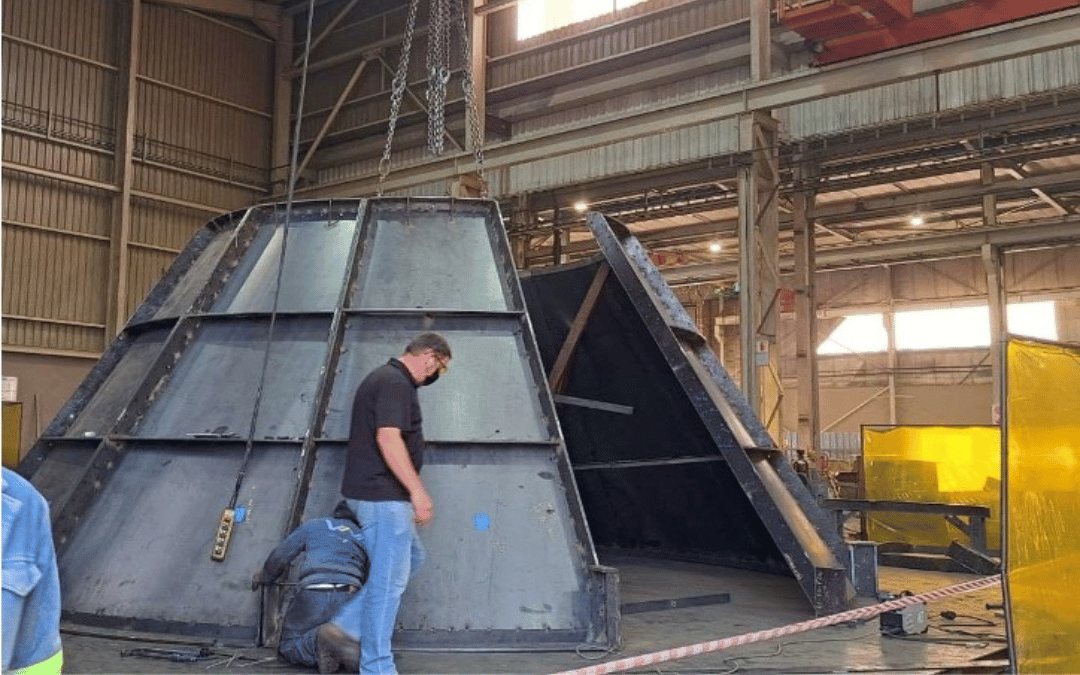
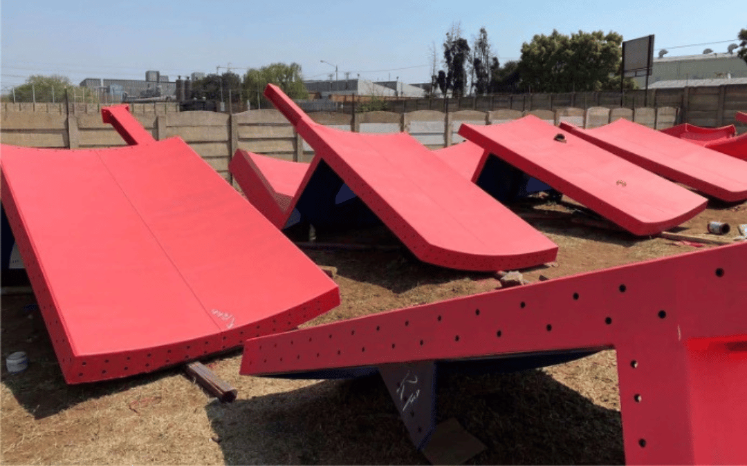
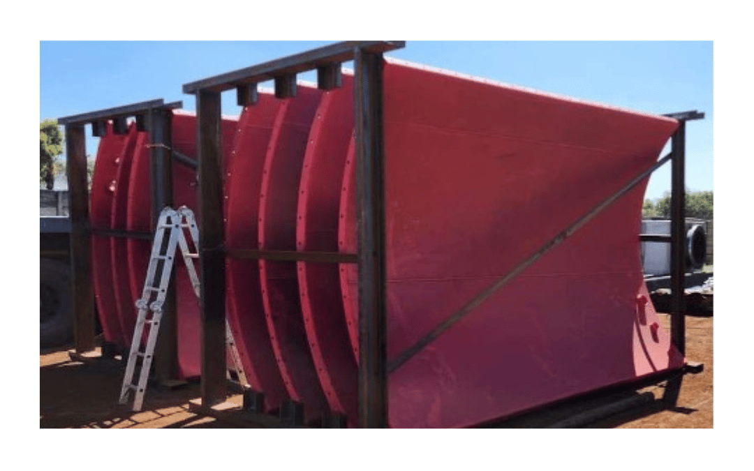
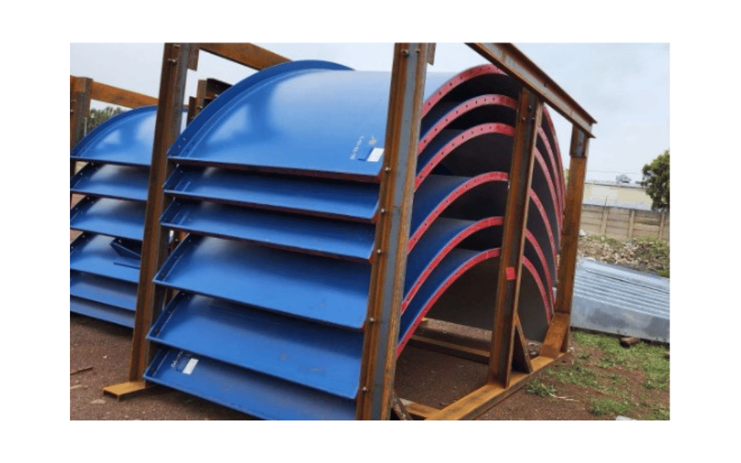
• To design the vessel as a bolted structure to ensure transport and erection constraints were met.
• Geometry to support platform above and all mechanical equipment including agitator and pumps.
ENGINEERING CONSIDERATIONS:
• Design of the vessel considered permanent loads, material loads, wind loads as well as loads due to equipment.
• Due to the nature of the spliced connections these had to all be modelled in detail, including all the bolts.
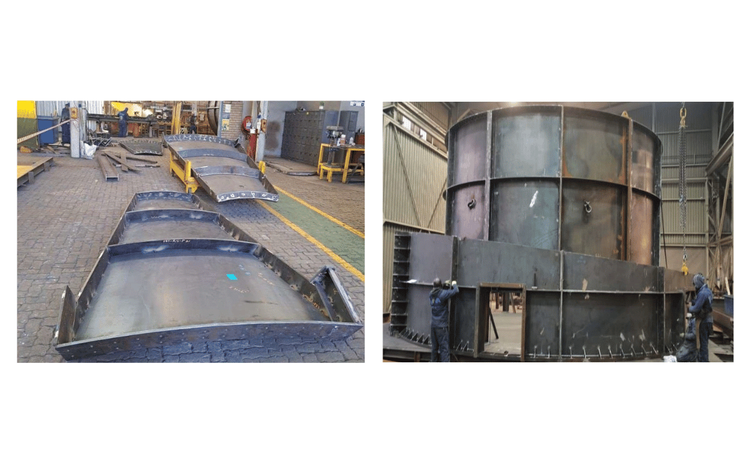
• Since the vessel was to be transported and erected piece by piece and due to the size of each piece, a lifting study had to be performed.
• Some of the engineering considerations included in the lift study were:
• Selecting the most appropriate lifting methodology
• Analysis of the larger launder elements in the lifting/suspended arrangement.
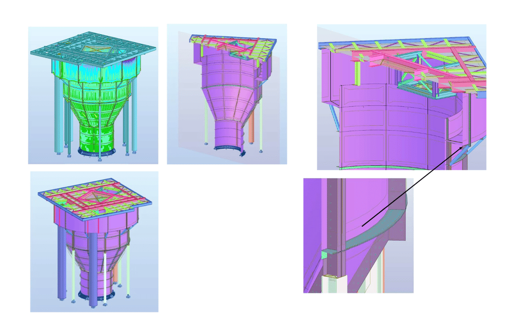
The splices or connections between each piece of the structure also form the stiffeners required for out of plane forces due to the geometry (such as at the transition points between cylindrical and conical forms) and externally applied loads (such as the supported platform, wind and equipment loads). Major areas of stress such as the transition points therefore had two plates forming the stiffener as these were also splice locations. This allowed for significant reinforcement which adequately reduced stresses.
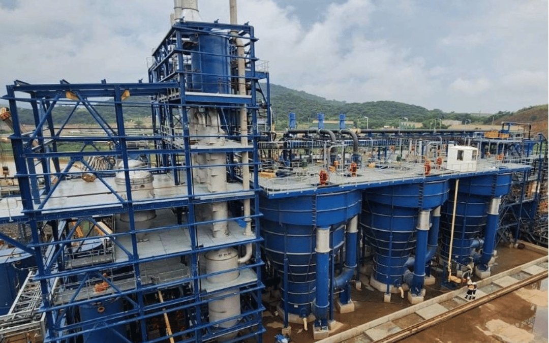
The integrated launder is supported directly off the main vessel structure and the cantilever is supported by a series of knee braces tying it back to the main vessel walls. An additional ring of stiffeners are provided at this level to reinforce
the main vessel walls against this out of plane load.
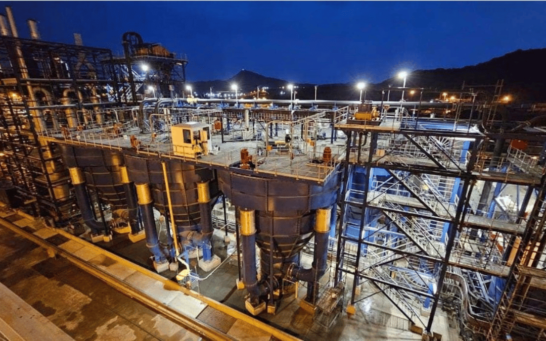
The ring of columns at the top transition point reduces the load from the launder and supported platform on the lower portion of the vessel. This allows the vessel to carry the fluid loads more economically where they are at their maximum.
These columns were aligned to the vertical splice and stiffener locations to adequately carry and distribute the stresses into the vessel shell. The vertical pipes coming off the launder were modelled as loads only and did not support the structure.